Description
DDS digital signal synthesis, excellent audio, on-board stereo and RDS
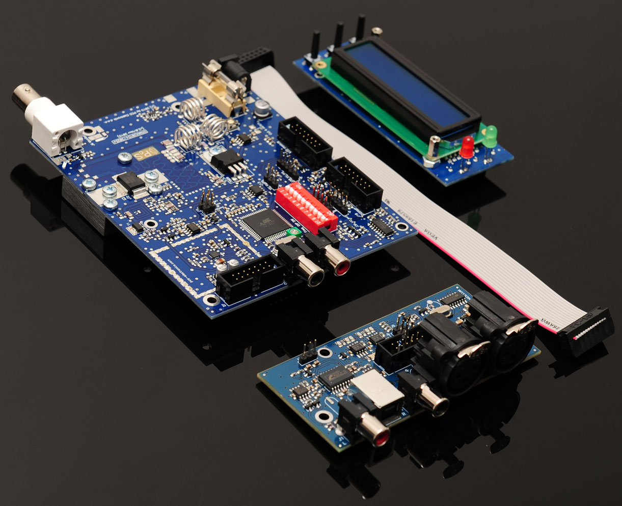
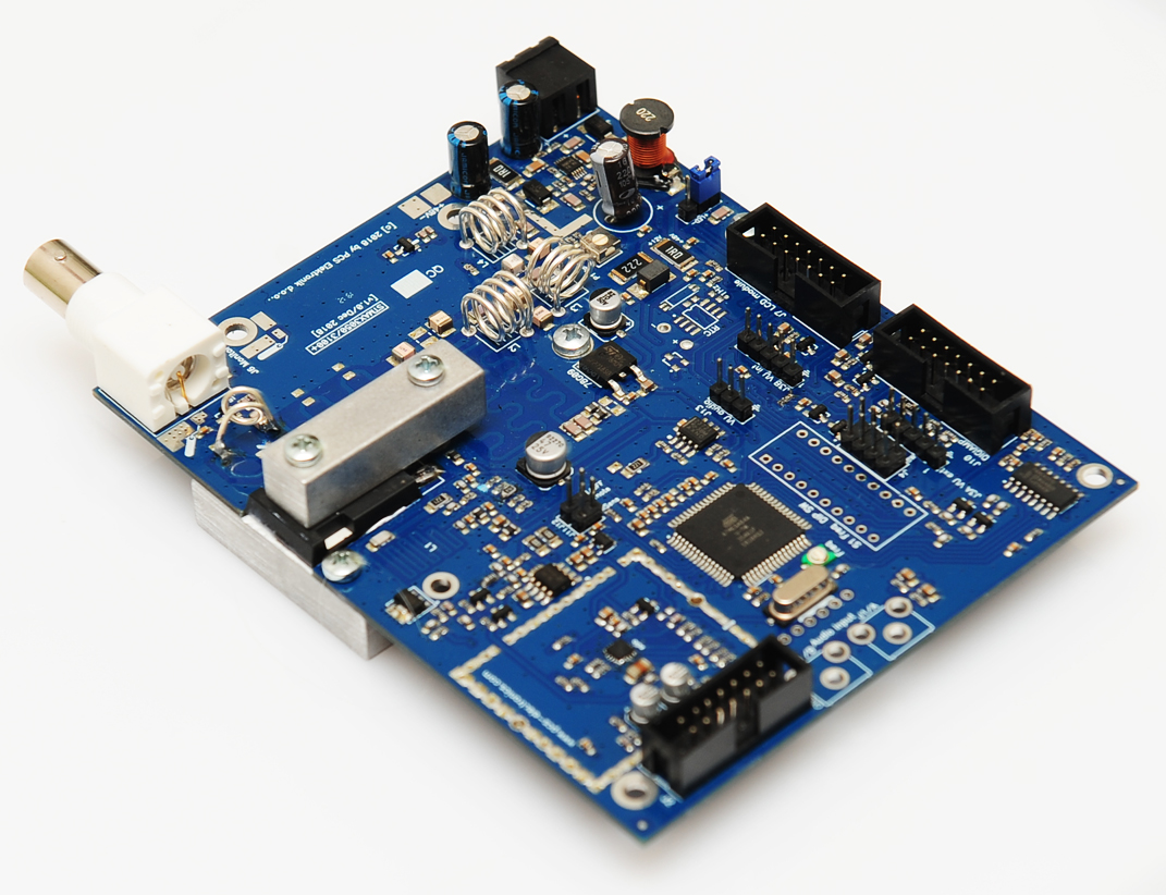
The new STMAX 3000+ series FM exciters combine more features into a small board than ever before. With DDS digital modulator, on-board stereo and RDS and all of this full controllable via LCD display with new 2-level MENU system and availability in 15W, 25W and 50W formats all powered from 12-15V and 100W model powered from 48V this board represents realization of dreams for most prospective radio station builders.
The design of the STMAX 3000+ series is based on MAXPRO6015+ and also looks quite similar at first glance, however it comes with on-board DDS modulator and DSP stereo encoder with RDS. The result is a rugged and solid FM exciter with completely flat
power output across the entire FM band at 15W, 25W, 50W or 100W designed to
run silently 24/7. Since the new design featuring larger heatsink was so much better and completely
stable we were able to add 50W and 100W models. Your dream FM exciter is a reality right now!
The exciter carries a one year limited warranty on parts and labor against defects in materials and workmanship, except the RF final transistor.
You can find the manual for this (and other products)
here.
How is STMAX3000 series different from the MAXPRO8000 series?
– On-board stereo and RDS encoders.
– New larger heatsink
– DDS digital modulator. This ensures very good audio, but creates spurious artefacts about -50dBc
– All parameters adjustable from the LCD, including RDS RT, PS, PI and others
– 2- level menu system groups similar parameters together making adjustment easier
– Comes also with new LCD with rotary encoder. This new LCD offers password protection and other cool features.
– Can’t be used with MPX STL links as there is no MPX in
Technical specifications:
– RF Output Power: 0 to 15 Watts, 0-25W, 0-50W, 0-100W (fully variable via LCD in nice gradual steps), LCD power adjustment range can also be limited to 0-1W, 0-2W, 0-3W, 0-4W … 0-15W, 0-full, this is done with a jumper (exact options vary depending on model).
– Output connector: BNC female
– Output Impedance: 50 Ohms
– Frequency range: 87.5-108MHz
– PLL Steps: 100KHz-500KHz, adjustable
– Frequency stability: +/- 20Hz
– Spurious/Harmonic rejection: Harmonics: >50dB, Spurious: >-50dBc
– Power Supply 15W: 12-15V/2.5A
– Power Supply 25W model: 12-15V/4.5A
– Power Supply 50W model: 12-15V/6A
– Power Supply 100W model: 48V/4A
– Power connector 15W, 25W, 50W and 100W model: New design with plugin with 2 screw terminals or standard barrel with 2.1mm positive center pin
– Quartz Locked PLL Frequency Control, DDS digital modulator
– No Expensive Test Equipment Required
– Audio performance: Less than 0.1% distortion, 20Hz-15KHz
– RF output ruggedness: SWR protection, temp protection
– Polarity protection, temp protection
– Pre-emphasis, 50uS, 75uS or none selectable via LCD
– Stereo pilot level adjustable via LCD
– RDS pilot level adjustable via LCD
– MPX level adjustable via LCD
– Audio Input Impedance: 1Kohm, unbalanced
– Audio Input Level: -10dBu, +4dBu (selectable from LCD)
– Stereo separation: >50dB
– S/N ratio: >90 dB
– PC Board Size: 100x125mm
– Audio connectors: 2x RCA jack, 14-pin connector for external input board with balanced XLR inputs
– RF monitor: solder pads
What is the Predrilled LCD front panel?
– This is a rectangular piece of aluminum with predrilled holes for LCD display, 3 buttons and LED diodes. It also has 4 holes in the corner so you can easily mount this to your case. This makes it much easier to mount the transmitter into a nice looking case (eliminates the hard work with the LCD). This is of course an optional item.
What is the RS232/USB IO board and why do I need it?
IO board is required, if you want to control STMAX3000+ remotely via PC. It plugs into the LCD control module.
What is the Ethernet remote control module for?
This add-on card lets you connect this transmitter to the PC via Ethernet network. You can control and monitor the status of your transmitter over Ethernet or Internet. This is of course an optional item.
What is the Audio Input Board for?
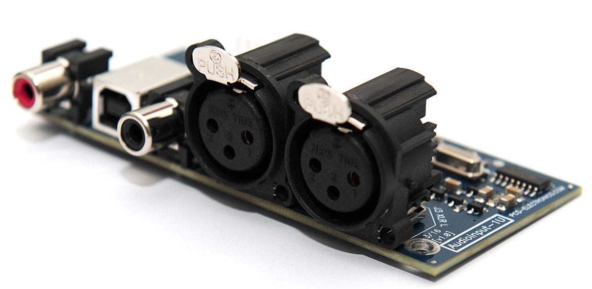
This add-on card adds two XLR balanced inputs and two RCA connectors plus USB audio input. It also comes with extra low pass filter, limiter and selectionable optional external input (mp3 player or something else). The inputs are ESD protect and have RF filter. This is of course an optional item but it is highly recommended and it does make life easier as you can install exciter far from the input connectors.
What is the Software+IOBOARD for changing logo?
This is a combination of special unlocked version of software and RS232 IO board, which is required to control STMAX3015+ remotely via PC/RS232. It plugs into the LCD control module. Software lets you change welcome text (logo); you can replace that text with your company name for example. Your customized text will be saved and used at every power-up. This is of course an optional item.
What is modification with software for 76-108MHz?
This is the microcontroller IC with modified software that enables STMAX units to work from 76MHz to 108MHz. In order to use this you have to remove original IC from LCD control module (it is in a socket) and place this modified. Immediately frequency range will be expanded. You can change back to the standard IC at any time. This item can be purchased separately and it will also work with STMAX units that you purchased in the past (unless they are really old). Make sure to take correct version for your display! Important: The LCD shows less power than there actually is available below 76MHz. Also actual output power may be a bit less under 87MHz, how much depends on the board but usually about 20-30% less at 76MHz. Also the LCD itself will show less power than there actually is being transmitted. So keep in mind that your display will show maybe 5W but 10-12W will be transmitted.
What is the Empty enclosure for STMAX3050 for?
This is a very practical enclosure with all holes predrilled. You can install the STMAX3015 inside. It even has a heatsink so it will accept even the 25W, 50W or 100W version. A fan is not included, use 80×80 fan. Holes for the LCD are predrilled as well. No text or brand name is printed anywhere on this box. Look at the video below:
What else should I buy to construct a big 500W or 1000W or higher transmitter?
We really recommend these items to all users:
– One of our filters, more info on these available here. those with DIGIAMP are easier to connect (use digiamp flat cable).
– Any of these pallets here, a power supply for these can be purchased here
– A rack enclosure from 1H to 3H, with fans, accessories and more…
– Use PTFE RG142 50 ohm coax for internal connections inside your rack (PTFE coax is easier to work with, it does not melt when hot). Make sure all coaxial cable leads are very short.
– Warning: Only suitable for remote areas
To look for a suitable antenna check: here.
To look for a suitable coaxial cable check:
here.
To look for a suitable case check:
here.


Reviews
There are no reviews yet.