FM receiver with TDA7000
Posted: Wed Dec 15, 2004 5:36 pm
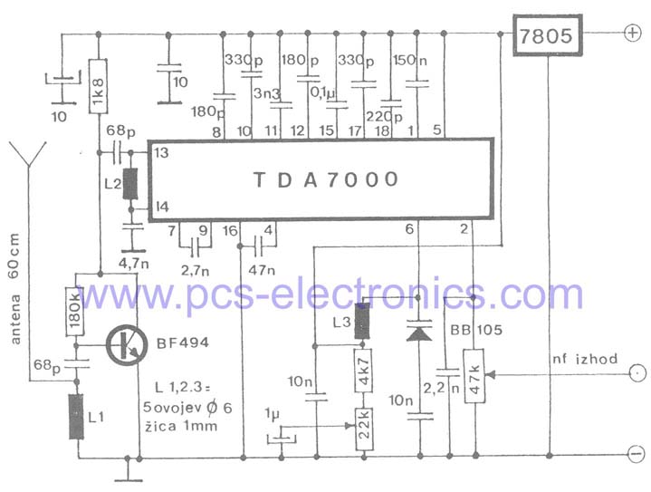
I tried to build a FM Reveiver according to the given schematic (http://www.pcs-electronics.com/schematics/Tda7000Rx.jpg).
The frequency adjustment doesnt work and i think i know why:
It seems that the whole oscillating circuit is wrong. The 22k potentiometer is between the +5V and 0V and the output only goes to a 1uF Capacitor. So it doesnt have something to do with the frequency....
Am i right?
My solution was a redesign of this part: the output of the potentiometer goes between the varicap diode and the 10nF Capacitor. I also connected the whole ocillation circuit to +5V instead of 0V.
If somebody wants to see my solution, please tell me and i make a scan.
Christian
