Page 1 of 1
Help with SWR protection circuit
Posted: Sat Dec 29, 2007 4:15 pm
by seven
Whats the best way to incorporate this on a band 2 amplifier?
Anyone got any schematics or docs handy?
is it best to just turn down/off the bias supply to the driver transistor (im using blf244 driving sd1407) or bypass the exciter into a 50ohm resistor.
I actually have an amp here with swr pickup and a diode going into a pot then into the base of a transsitor with the emitter grounded. Im not exactly sure how to use it because its not complete. The collector goes through a ferrite then onto a solder pad not connected to anything.
so when the swr is too high the emmiter will become ground, how do i use this to turn down the bias?
any help would be great.
thanks
Posted: Sun Dec 30, 2007 2:33 pm
by pcs
Either works well. Pulling the bias voltage down or cutting off the drive.
Just make sure your amplifier is stable with exciter output turned off, especially
if it still produces small amount of power.
Some flimsy RF AMP designs can oscillate under such conditions.
Posted: Sun Dec 30, 2007 2:57 pm
by seven
pcs wrote:Either works well. Pulling the bias voltage down or cutting off the drive.
Just make sure your amplifier is stable with exciter output turned off, especially
if it still produces small amount of power.
Some flimsy RF AMP designs can oscillate under such conditions.
thanks for that.
like i say, on the circuit that is already on the amp, the transistor collector on the swr circuit becomes ground when swr is high can i use this to turn the bias down? im now sure how it would be done or what the best way of doing it is.
I cant find anything on the net except one design using a relay.
hopefully i can get this going with your help
Posted: Sun Dec 30, 2007 3:23 pm
by pcs
You need forward/reflected power measuring circuit. Its basically
a SWR meter without a box and the display meters.
Or skip the trouble and use this:
http://www.pcs-electronics.com/output-b ... -1116.html
or this one with built-in filter and pull-down transistor that can be often
connected directly to the amp to pull-down bias:
http://www.pcs-electronics.com/lpf3000- ... -1123.html
Posted: Sun Dec 30, 2007 3:48 pm
by seven
I already have the SWR pickup strip which goes low when the SWR gets high . Im just not sure how to use it to pull the bias voltage down, where to connect it on the bias circuit etc. I cant just short out the regulator supplying the bias voltage.
Posted: Sun Dec 30, 2007 4:24 pm
by pcs
That depends on the particular biasing scheme used.
With other words, it varies from case to case a lot.
Posted: Sun Dec 30, 2007 5:34 pm
by seven
This is the bias circuit to the base of the BLF244:
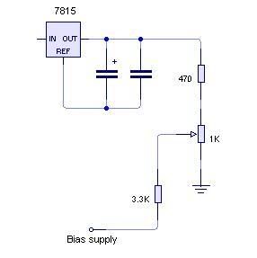
Posted: Sun Dec 30, 2007 5:37 pm
by pcs
Try to pull down the middle contact of the trimmer.
Make sure your leads are biased with a few caps to the ground,
such as 100pF+1nF, especially if long.
Posted: Tue Jan 08, 2008 2:33 am
by seven
Thanks Marko, this seems to work fine.